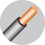
loading
Technical data

Conductors & Fibers

CONDUCTORS

Copper conductors are generally preferred for instrumentation cables for a better signal transmission, while, special alloy conductors are employed for thermocouple / compensating cables. Conductors are generally in accordance with EN 60288:

CLASS 1 - SOLID

CLASS 1

SOLID

CLASS 2 - STRANDED

CLASS 2

STRANDED

CLASS 5 - FLEXIBLE

CLASS 5

FLEXIBLE

Type of conductors are chosen according to the electrical characteristics, the required flexibility, the type of connection systems, or specific installation conditions, such as:

  • the class 5 flexible conductor is preferred in case of vibration, movement or reduced bending radius,
  • class 1 solid conductor is employed for permanent installation, crimping termination
  • tinned conductor is used in presence of corrosive atmosphere, high temperature or to facilitate the soldering


COPPER CONDUCTORS SQMM - EN IEC 60228 standard

COPPER CONDUCTORS AWG

FIBRES

For the manufacturing of optical cables, are generally used both multimode and single-mode fibres.


FIBRES
  • Singlemode fibres (9.5/125), are used for urban telephone lines and premises (FTTH) for video transmission (CATV), telecommunications and intelligent traffic networks.
  • Multimode fibres (50/125 and 62.5/125), are used for data transmission in short length transmissions and for transmission capacity up to 10 Gb/s.

TRANSMISSION PARAMETERS

Attenuation

What is it
Attenuation indicates the power loss of a light pulse going through an optical fibre having a certain length. The signal reduction, due to dispersion and absorption phenomena, has an exponential decay based on the fibre length. The ratio between the outlet power and the inlet power, expressed in a logarithmic function, represents a quantity linearly depending on the fibre length. Such a quantity is expressed in dB/Km. This is defined as intrinsic attenuation depending on the type of fibre and on its length. However, if a fibre is subject to side pressure (microbending) or to narrow bending radius (macrobending), the attenuation can undergo even drastic increments.
Attenuation is the most important parameter to be kept under control while manufacturing and laying optical cables.
The cable manufacturer must guarantee, during those phases, the prescribed attenuation levels.

How to measure it
The measuring methods for the attenuation are essentially three: reflectometric method, measurement with power meter and cut-back method or spectral attenuation method. The first two methods use monochromatic light sources and therefore measure only at the fixed wavelengths (850, 1300,…nm), while the third method allows to measure the attenuation for each wavelength of the spectrum of interest (800 – 1650 nm).

OTDR (optical time domain reflectometers)

It consists in measuring the backscattered power, due to the Rayleigh effect, of a light pulse, with a defined wavelength, injected into a fibre. Each fibre section reflects in every direction a light pulse going through it. The part of the signal that is reflected backwards is measured by the instrument that, on the basis of the delay, redefines the attenuation map according to the fibre length.
The measuring speed, the possibility of measuring on one end only, the possibility to carry out length measurements and to analyze the trend and the events localized along the whole length, make this method the most common and the most reliable one.
It is in fact used to measure during all the cable constructive phases, in the manufacturing testing sizes and on the laid sections.
The picture shows an OTDR  measurement graph, with the following information:

  • fibre length delimited by two reflection peaks (A);
  • measured section delimited by two inner markers (B);
  • absolute attenuation of the measured section expressed in dB;
  • attenuation by length unit expressed in dB/km.

Attenuation How to measure it

CUTBACK or Spectral Attenuation
It consists in comparing, for each wavelength, the optical power transmitted by the measured fibre to the inlet optical power. Where, the meaning of inlet power is the power transmitted by a short initial section (approx. 2 m) of the same fibre to be measured (cutback), by keeping the launching conditions as unaltered. The measuring apparatus in this case (see picture) is formed by a white light source decomposed by means of a monochromator in the various spectral components, by a high-sensibility photodetector and by
the acquisition/processing system.

In the graph is shown an example of the measure carried out by this method, where the attenuation is calculated according to the following formula.

The need to access the two measuring ends, the cost and the delicacy of the instrumentation, make it a non-routine measuring method, mainly suitable to the fibre characterization and to the laboratory measures.

Attenuation
Attenuation

POWER METER

It consists in noting the signal level getting out of a fibre, injected by a monochromatic source, and comparing it with the inlet level that is achieved by cutting a short piece of fibre in the inlet side.
This method therefore requires a source and a meter and then the two ends of the fibres to be measured.
Normally, this method is used as a relative attenuation measure, that is to say to monitor the power variations transmitted by the fibre under test.

POWER METER

Dispersion

What is it
There are two types of dispersion: chromatic dispersion and modal dispersion. Both have an impact on the bandwidth limitation (quantity of transmittable data ) and are expressed in ps/(nm.km).

  • Chromatic dispersion, is the phenomenon causing a light pulse in a fibre to run at a speed that depends on its wavelength. Since perfectly monochromatic pulses do not exist in reality (even laser ones), the various pulse components, inside the fibre, run with their own speed and consequently, the pulse at the outlet is wider than the original one (the components close to the infrared slow down, the ones close to the ultraviolet accelerate). When two pulses, close to each other, interfere till they become indistinguishable, then you have a band limitation. See picture below.
    This phenomenon exists both for singlemode and for multimode fibres.
  • Modal dispersion, is only referred to MM fibres and is due to the differences in the transit time of the various modes in which the original pulse is decomposed. Since each mode covers optical paths with different lengths (and therefore with different times), the consequence is always the widening of the pulse and the consequent risk of band overlapping or limitation.
Dispersion

How to measure it
Main measuring methods are essentially three: MPS (modulation phase-shift), DPS (differential phase-shift) and PULSE-DELAY.
The first two methods require to access the two connecting heads and the use of complex instrumentation; as a consequence, the use on the field is not really feasible.
The third method, on the contrary, only requires to access one measuring head and uses compact instrumentation.

MPS, calculates the group pulse delay by measuring the phase displacement that is formed between a modulated pulse that goes through the section fibre and the original modulated pulse. The apparatus is mainly formed (see picture) by a modulated laser source and a vectorial RF network analyzer.
The MPS method measures the phase difference between a transmitted and received signal. The RF network analyzer modulates the amplitude of the laser’s signal.

DPS, is very similar to the previous one, except for the fact that, being equipped with a wavelength selector (see picture), it is possible to select very tight windows within the laser emission spectrum. In this way, it is possible to directly measure the chromatic dispersion on the basis of the wavelength.

Like the MPS method, the DPS method also modulates the amplitude of the laser’s signal. But the DPS method also slightly varies, or dithers, the laser’s wavelength.

PULSE-DELAY, is the quickest and most practical method and uses a CD-OTDR for the measurement. It is based on the principle that different wavelengths pulses travel at a different speed. By launching a multiple laser pulses into a fibre by means of a CD-OTDR and by analyzing the delay
of the pulses reflected by the end itself, it is possible to calculate the chromatic dispersion time. See picture.

SINGLEMODE FIBRE CHARACTERISTICS

Singlemode Step-Index Fibre

It presents a step-index profile, with a smaller core (8÷10 µm) compared to multimode fibres. In this situation only
a single mode (an axial ray) is allowed to travel through the fibre. This produces no pulse dispersion which essentially offers an infinite bandwidth.

Singlemode Step-Index Fibre

This type exhibits a distinct change in refractive index between the core and cladding, and so it is called step-index for this reason. Light is transmitted along a fibre by a multimode of different paths, ranging from one which is parallel to the axis
to those propagating at angles close to the critical angle, with many in between. Each path at a different angle is termed
a “transmission mode”. The distances travelled by various modes, and hence the time taken, are not equal. Consequently, a short pulse of light, launched simultaneously into many modes, will have various transmission delays, causing a pulse spreading (intermodal dispersion).

OS1 are first generation fibres.

OS2 are fibres with low water content, and therefore they allow to exploit a wider transmission spectrum.

The “Bend-insensitive” fibres are equipped with a particular index profile that makes them particularly insensitive to bendings.

  • Type “G657A” is optimized to operate at 1550 – 1625 nm,
    and therefore it is suitable to realize type FTTH connections.
  • Type “G657B” is equipped with a limited mfd and can therefore withstand even more extreme bendings and is suitable to make patch cord and connections that require narrow bending radius.

NZD fibres have an index profile similar to the Bend-insensitive, but with a bigger effective area (65 µm2) that, together with an optimized chromatic dispersion, make them suitable to DWDM transmissions in long distances connections with long and very long distances.

MULTIMODE FIBRE CHARACTERISTICS

Multimode Graded-Index Fibre
In a graded index fibre, the index of refraction of the core is highest in the centre and gradually decreases as the distance from the centre increases. In this way, the light rays are continually being bent towards the fibre optical axis, and this causesa reduction in dispersion.

OM1 are the standard 62,5 µm MM fibres. Because of the production process, the index profile shows a “hole” that creates troubles in the propagation modes, thus limiting the transmission length towards high frequencies. Suitable for LED sources.

OM2 are standard 50 µm MM fibres. They are realized by means
of a modified constructive process and show an index profile almost without discontinuity. Suitable for LED sources.

OM2+ they are similar 50 µm MM fibres, but optimized for bigger transmission lengths.

OM3 – OM4 are 50 µm MM with optimized index profile to minimize the modal dispersion (DMD) thus making these fibres suitable to use laser sources (VCESL) and therefore allowing transmissions on bigger lengths at higher frequencies.